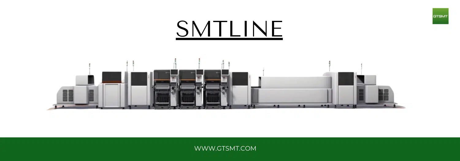
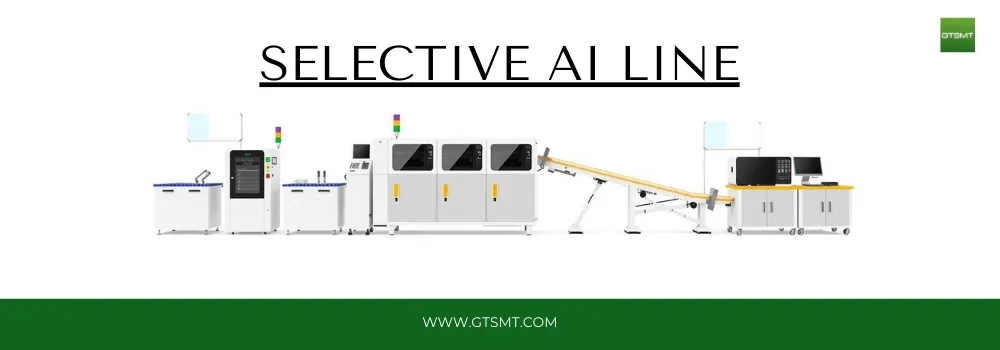
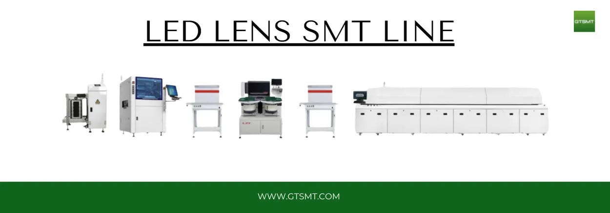
Introduction of Surface Mount technology
Table of Contents
Surface Mount Technology (SMT)
The development of SMT has led to big steps forward in designing and making electronics. It has made it easier to make circuits that are more complicated and closely packed together. This has led to devices getting smaller and more functions being packed into them. The goal of this book is to give you a full picture of SMT by talking about its background, its parts, design issues, production methods, and possible future developments.
In the next few chapters, we’ll look at different aspects of SMT. We’ll start by looking at its history and the main innovations that have shaped its growth. We will look at the basic SMT parts, like resistors, capacitors, and integrated circuits, and talk about what they do and how they work.
When it comes to SMT, design is very important because the layout and placement of parts have a direct effect on how well and reliably the end product works. This lesson will go over the basics of SMT design, such as how to choose materials, use design tools, and keep heat under control.
SMT manufacturing is a complicated and exact process with many steps, such as applying solder paste, placing components, and then soldering them together. We’ll go over each step of the process in great depth, pointing out the tools and methods that are used to make sure the results are always good.
Quality control is very important in SMT manufacturing because any flaws can cause big problems with how the product works or even cause it to fail. We will talk about the ways and tools that are used to test and check SMT assemblies, as well as the problems that often come up and how to fix them so that quality control is reliable.
Different fields, like consumer goods, automotive, aerospace, and healthcare, use SMT in different ways. We will talk about the specific ways that SMT is used in these areas and show how it has helped make new and better computer systems possible.
We will look ahead to the future and talk about the new tools and trends that will shape how SMT changes over time. There are a lot of exciting things that could happen in the future of SMT, from better materials and manufacturing methods to using AI and machine learning in production.
Lastly, we will talk about how SMT affects the world and what is being done to lessen those effects. As the electronics industry grows, it is important to think about how to make manufacturing more sustainable and how long gadgets last.
The people who should read this book are engineers, artists, students, and anyone else who is interested in electronics and SMT. Whether you are new to Surface Mount Technology or want to learn more about it, this complete guide will help you find your way around the world of this important technology.
Chapter 1: Introduction to Surface Mount Technology (SMT)
Surface Mount Technology (SMT) is a big step forward in the business of making gadgets. In standard through-hole technology, component leads are inserted into holes that have been drilled in a PCB. SMT, on the other hand, mounts components directly onto the board’s surface. This method makes it possible to have more components on a smaller PCB and improve speed.
SMT has its roots in the 1960s and 1970s when people started to want electronics that were smaller and would work better. Engineers and makers tried to make electronic assemblies smaller and lighter while still making them more useful. SMT was the answer; it made it possible to make electrical systems that were smaller and worked better.
One of the best things about SMT is that it lets you put parts on both sides of the PCB, which makes a lot more room for circuits. This is especially important in today’s electronics, where gadgets should be small, light, and full of features. Also, SMT parts are usually smaller and have shorter leads than their through-hole peers. This helps cut down on signal propagation delays and improves the overall performance of the circuit.
There were some problems with the change from through-hole technology to SMT. In the early days of SMT, makers had to spend a lot of money on new tools and training, and they had to come up with new ways to handle and place smaller parts. But the pros of SMT quickly trumped the cons, and the technology quickly became the norm for putting electronics together.
SMT is now used to make a lot of different kinds of electronics, from computers and smartphones to medical devices and car systems. Technology has made it possible to make circuits that are more complex and reliable. This has led to progress in many areas, such as telecommunications, computing, and consumer goods.
This chapter will talk about the basic ideas behind SMT. It will cover the different kinds of parts that are used, how to create SMT assemblies and the main steps that are taken during the manufacturing process. We will also talk about the benefits of SMT over standard through-hole technology and show you the places where SMT has made the biggest difference.
Types of Components Used in SMT
SMT parts come in many sizes and shapes, and each one is made to do a specific job in an electrical circuit. These are the most popular types of SMT parts:
- Resistors: These parts are used to stop the flow of electricity in a circuit. Because SMT resistors come in a range of resistance values and power levels, they can be used in a lot of different situations.
- Capacitors: Capacitors store and release electricity, which keeps computer circuits stable and clean. Because different designs need different capacitance and voltage levels, SMT capacitors come in a range of sizes.
- Inductors: When you use an inductor to filter something or store energy, it stores that energy in a magnetic field. There are different inductance numbers and current ratings for SMT inductors.
- Diodes: Diodes allow current to flow in one direction only, providing protection and rectification in circuits. SMT diodes are used in circuitry that control power, process signals, and keep things safe.
- Transistors: Transistors make electrical signals stronger and allow them to change. There are different kinds of SMT transistors, such as field-effect transistors (FETs) and bipolar junction transistors (BJTs).
- Integrated Circuits (ICs): ICs are complicated devices made up of many electronic parts that are all put together in one box. Microprocessors, memory chips, and application-specific integrated circuits (ASICs) are all types of SMT ICs.
Design Considerations for SMT Assemblies
When designing an SMT assembly, there are a few important things to keep in mind to make sure the end product works well and is reliable. Some important parts of the plan are:
- Component Placement: The placement of components on the PCB must be carefully planned to optimize space and minimize signal interference. Designers use computer-aided design (CAD) software to create precise layouts and ensure proper alignment of components.
- Thermal Management: Putting parts on the PCB needs to be carefully thought out so that room is used efficiently and signal interference is kept to a minimum. Computer-aided design (CAD) software helps designers make accurate plans and make sure that all the parts are lined up correctly.
- Soldering Techniques: Soldering is the only way to ensure that the electrical links between the PCB and the components are stable. In SMT manufacturing, different types of soldering, like reflow soldering and wave soldering, are used to make high-quality parts.
- Material Selection: The efficiency and durability of the assembly are affected by the materials used for the PCB and its parts. When designers choose materials, they look at things like how well they conduct heat, how they conduct electricity, and how strong they are.
- Testing and Inspection: To make sure that SMT assemblies are of good quality and work properly, strict testing and inspection methods are used. X-ray inspection and automated optical inspection (AOI) are two common ways to find flaws and make sure that solder joints are solid.
Key Steps in the SMT Manufacturing Process
The SMT manufacturing process involves several stages, each critical to achieving a high-quality final product. The key steps include:
- Solder Paste Application: A stencil is used to put solder paste, which is a mix of solder powder and flux, on the PCB. This step makes sure that the solder paste is put precisely on the pads where the parts will go.
- Component Placement: Pick-and-place machines, which are automated, put SMT components correctly on the PCB. Vision systems in these tools make sure that the parts are lined up and orientated correctly.
- Reflow Soldering: The PCB with the parts on it is put into a reflow oven, where the solder paste melts and hardens to make strong electrical connections. The oven’s temperature profile is carefully managed to keep parts from getting damaged by heat.
- Inspection and Testing: Once the soldering is done, the PCB is inspected and tested to find any problems or flaws. AOI and X-ray inspection are used to check the quality of the solder joints. Functional testing makes sure that the assembly works the way it’s supposed to.
- Final Assembly: The PCB is put together in its final shape. This may include extra steps like conformal coating, mechanical assembly, and final testing.
Advantages of SMT over Through-Hole Technology
- Smaller PCB Size: SMT lets you use more components per square inch, which lets you make PCBs that are smaller and more compact. This is very important for modern electronics like smartphones and wearable tech that need to take up little room and weight.
- Better Performance: Because SMT parts have shorter lines and are smaller, their inductance and resistance are lower. This means that signals are sent more quickly and accurately. This is very important for apps that use high frequencies.
- Increased Reliability: Because SMT parts are fixed directly on the PCB’s surface, they are less likely to break under mechanical stress. This makes computer assemblies last longer and work better, especially in places where vibrations or mechanical shocks are common.
- Automated Assembly: SMT works well with manufacturing methods that use machines. Pick-and-place machines and reflow soldering methods make production more efficient, cut down on labour costs, and lower the chance of mistakes made by people.
- Double-Sided Assembly: Components can only be put on one side of the PCB with this method. SMT, on the other hand, lets components be put on both sides of the board. This makes the best use of the room you have and lets you make more complicated designs.
- Cost-Effectiveness: Specialised equipment is needed for SMT, which can make the setup costs high at first. However, the total production costs are usually lower when making a lot of things. Costs are cut because less material is used and things are put together faster.
- Flexibility in Design: SMT can work with many different kinds of parts and sizes, which gives PCB designers more options when they’re making boards. Chip-scale packages (CSPs) and ball grid arrays (BGAs) are two types of packages that designers can choose from based on the needs of the application.
Applications of SMT in Modern Electronics
Surface Mount Technology is ubiquitous in the electronics industry, finding applications in numerous sectors:
- Consumer Electronics: SMT is an important part of making smartphones, tablets, laptops, and other items for everyday use. The technology makes it possible to put high-performance parts into small, movable gadgets.
- Automotive Electronics: Today’s cars depend on complex electrical systems to do things like control the engine, navigate, entertain, and keep the passengers safe. SMT helps make it easier to make electronics for cars that work well and are reliable, even in harsh circumstances.
- Medical Devices: SMT is used to make medical devices like monitoring systems, diagnostic tools, and devices that are implanted. Medical gadgets can be made smaller with this technology, which makes them easier for patients to use and less invasive.
- Industrial Automation: SMT is very important in industrial automation and control systems that need strong and reliable electrical parts. Automated machine controls (PLCs), sensors, and actuators all use SMT-based assemblies.
- Aerospace and Defense: The aerospace and defense industries demand high-reliability electronic systems capable of operating in extreme conditions. SMT provides the necessary performance and durability for avionics, satellite communications, and defense electronics.
- Telecommunications: SMT is an important part of making routers, switches, and mobile base stations, which are all types of communication devices. Modern phone networks need to be able to process data quickly and make sure that signals are always correct. This technology serves those needs.
- Wearable Technology: The market for wearable tech like fitness trackers and smartphones is growing, and SMT can help by making electronics that are small, light, and have advanced features.
Future Trends in SMT
As the electronics industry continues to evolve, several emerging trends are poised to influence the future of Surface Mount Technology:
- Miniaturization and Integration: People want electronics that are smaller and more powerful, so SMT components will get even smaller and more functions will be put into single packages. This trend will continue because materials and industrial methods are getting better.
- Advanced Materials: The creation of new materials, like high-performance substrates and conductive inks, will make SMT systems work better and last longer. These materials will make it possible to make electronics that work better and are better for the world.
- Artificial Intelligence and Machine Learning: AI and machine learning technologies are being added to SMT manufacturing processes to make quality control better, make production methods more efficient, and cut down on mistakes. Intelligent systems can look at data in real time to make changes and guess what problems might happen.
- Flexible and Wearable Electronics: As flexible and wearable electronics become more popular, new SMT solutions will be needed to deal with the unique problems that come up with substrates that can be bent and stretched. The next wave of flexible devices will depend on SMT in a big way.
- 5G and Beyond: The rollout of 5G networks and the creation of new communication technologies in the future will need high-performance SMT parts that can handle faster data speeds and less latency. SMT will be very important for supporting the networks and gadgets for advanced communication.
- Sustainability and Environmental Considerations: As the electronics business focusses on sustainability, making products in ways that are better for the environment and recycling electronic waste will become more important. SMT processes will change over time to have less of an effect on the world and support the ideas of a circular economy.
Environmental Impact of SMT
As the electronics industry grows, it is important to think about how Surface Mount Technology affects the world. Taking care of the environmental problems that come with SMT includes a few main areas:
- Material Selection: Choosing PCBs and parts made from eco-friendly materials can lower the impact of SMT systems on the environment. Some materials that keep dangerous substances to a minimum are lead-free solder and halogen-free laminates.
- Waste Reduction: Using automated tools and manufacturing methods that are more efficient can cut down on waste and energy use. Using lean manufacturing concepts and improving the way things are made can help the environment.
- Recycling and Disposal: To lessen the damage that SMT does to the earth, it is important to recycle and get rid of electronic waste the right way. Important steps include coming up with ways to get useful materials back from old electronics and reducing the amount of trash that ends up in landfills.
- Energy Efficiency: Making SMT manufacturing methods and equipment more energy efficient can cut down on greenhouse gas emissions and lower costs. For sustainable output, it is important to put money into technologies and methods that use less energy.
- Lifecycle Management: Looking at all the stages of an electronic product’s life, from planning and making it to using it and throwing it away, can help you find ways to make it more environmentally friendly. Electronics last longer and produce less trash when they are made to be durable, repairable, and recyclable.
As the electronics industry grows,
it is important to think about how Surface Mount Technology affects the world. Taking care of the environmental problems that come with SMT includes a few main areas:
- Smartphones and Tablets: Choosing PCBs and parts made from eco-friendly materials can lower the impact of SMT systems on the environment. Some materials that keep dangerous substances to a minimum are lead-free solder and halogen-free laminates.
- Laptops and Ultrabooks: Using automated tools and manufacturing methods that are more efficient can cut down on waste and energy use. Using lean manufacturing concepts and improving the way things are made can help the environment.
- Smart Home Devices: To lessen the damage that SMT does to the earth, it is important to recycle and get rid of electronic waste the right way. Important steps include coming up with ways to get useful materials back from old electronics and reducing the amount of trash that ends up in landfills.
- Wearable Devices: Making SMT manufacturing methods and equipment more energy efficient can cut down on greenhouse gas emissions and lower costs. For sustainable output, it is important to put money into technologies and methods that use less energy.
- Gaming Consoles and VR Headsets: Looking at all the stages of an electronic product’s life, from planning and making it to using it and throwing it away, can help you find ways to make it more environmentally friendly. Electronics last longer and produce less trash when they are made to be durable, repairable, and recyclable.
Case Studies of Successful SMT Implementations
To show how Surface Mount Technology has changed things, we will look at a few examples of great SMT implementations in different fields. These case studies will show the problems that were encountered, the ways that they were fixed, and the results that were reached by using SMT.
Case Study 1: SMT in Automotive Electronics Problems: Making things smaller, making sure they work well, and keeping the temperature down.
- Advanced thermal analysis, automatic inspection, and careful choice of components are the solutions.
- Results: Electronic control units (oecus) in cars work better and are more reliable.
Case Study 2: SMT in Medical Devices Problems:
Making devices smaller, making sure they are biocompatible, and following the rules.
- Answers: Use products that are biocompatible, test them thoroughly, and follow medical standards.
- Results: The creation of small, dependable medical gadgets like sensors that can be implanted and monitoring tools.
Challenges in Case Study 3:
SMT in Consumer Electronics is high-performance, small in size, and low-cost.
- Solutions: Using high-tech parts, automatic production, and low-cost materials together.
- Results: The production of high-performance smartphones and tablets with more features and lower prices of production.
- This is a list of SMT terms and acronyms.
- There will be a full glossary of SMT words and acronyms given to help readers understand the technical language used in the field of Surface Mount Technology. The terms in this glossary will come in handy for students, engineers, and artists.
- This complete guide is meant to help you fully understand Surface Mount Technology, from its basic ideas to its uses and possible future developments. This book will help you find your way in the constantly changing world of SMT, no matter how long you’ve been working in the field or how new you are to it.
This is a list of SMT terms and acronyms.
There will be a full glossary of SMT words and acronyms given to help readers understand the technical language used in the field of Surface Mount Technology. The terms in this glossary will come in handy for students, engineers, and artists.
This complete guide is meant to help you fully understand Surface Mount Technology, from its basic ideas to its uses and possible future developments. This book will help you find your way in the constantly changing world of SMT, no matter how long you’ve been working in the field or how new you are to it.
Chapter 2: History and Evolution of SMT
Surface Mount Technology (SMT) has undergone significant evolution since its inception, transforming the landscape of electronic manufacturing. This chapter will explore the historical development of SMT, tracing its roots from the early innovations in electronics to its current status as the dominant technology in electronic assembly.
Early Innovations in Electronics
The history of electronics dates back to the late 19th and early 20th centuries, with the invention of the vacuum tube and the development of radio technology. These early innovations laid the foundation for modern electronics, enabling the creation of amplifiers, oscillators, and other fundamental electronic circuits.
Early Innovations in Electronics (continued)
The advent of the transistor in the late 1940s marked a pivotal moment in the history of electronics. Invented by John Bardeen, Walter Brattain, and William Shockley at Bell Labs, the transistor replaced bulky and fragile vacuum tubes with a smaller, more reliable, and energy-efficient device. This breakthrough paved the way for the miniaturization of electronic circuits and the development of modern semiconductor technology.
The Rise of Integrated Circuits
The next major milestone in the evolution of electronics was the development of the integrated circuit (IC) in the late 1950s. Jack Kilby of Texas Instruments and Robert Noyce of Fairchild Semiconductor independently invented the IC, which combined multiple transistors and other components onto a single silicon chip. This innovation revolutionized electronic design and manufacturing, allowing for the creation of more complex and compact circuits.
Integrated circuits quickly became the building blocks of electronic devices, leading to the development of microprocessors, memory chips, and other critical components. The IC era also saw the rise of printed circuit boards (PCBs) as a standard platform for assembling electronic components. Through-hole technology, where components’ leads are inserted into holes drilled in the PCB and soldered in place, became the dominant method of assembly.
The Emergence of Surface Mount Technology
By the 1960s and 1970s, the demand for smaller, lighter, and more reliable electronic devices continued to grow. Traditional through-hole technology faced limitations in meeting these demands due to the size and lead length of components. To address these challenges, engineers began exploring new assembly techniques that would eventually lead to the development of Surface Mount Technology.
The concept of surface mounting involved placing components directly onto the surface of the PCB without the need for drilled holes. This approach allowed for higher component density, reduced parasitic inductance and capacitance, and improved performance. Early SMT components, known as surface-mount devices (SMDs), were designed with shorter leads or leadless packages, making them suitable for high-frequency applications.
Key Innovations in SMT Development
Several key innovations in the late 20th century contributed to the widespread adoption of SMT:
- Development of SMDs: The creation of standardized SMD packages, such as chip resistors, capacitors, and integrated circuits, enabled the transition from through-hole to surface mount assembly. These components were designed to be smaller and easier to place on the PCB surface.
- Advancements in Soldering Techniques: The introduction of reflow soldering, a process where solder paste is applied to the PCB and then melted in a controlled oven, provided a reliable method for creating strong electrical connections between SMDs and the PCB. This technique replaced traditional wave soldering used in through-hole assembly.
- Automated Assembly Equipment: The development of automated pick-and-place machines revolutionized the SMT manufacturing process. These machines could accurately and rapidly place SMDs onto the PCB, significantly increasing production efficiency and reducing labor costs.
- Improved PCB Design Software: Computer-aided design (CAD) software became essential for designing complex SMT assemblies. These tools allowed engineers to create precise layouts, optimize component placement, and simulate thermal and electrical performance.
The Transition to SMT
The transition from through-hole technology to SMT was driven by the need for smaller, faster, and more reliable electronic devices. In the 1980s and 1990s, SMT gained momentum as manufacturers recognized its advantages in terms of size reduction, performance enhancement, and cost savings.
Consumer electronics, telecommunications, and computing industries were among the first to adopt SMT on a large scale. The demand for portable and high-performance devices, such as mobile phones, laptops, and networking equipment, fueled the rapid growth of SMT. The ability to place components on both sides of the PCB further increased the design flexibility and functionality of electronic products.
Challenges and Solutions in SMT Adoption
The adoption of SMT was not without challenges. Manufacturers faced several technical and logistical issues, including:
- Component Handling: SMDs were smaller and more delicate than through-hole components, requiring specialized handling and placement techniques. Pick-and-place machines with advanced vision systems were developed to address this challenge.
- Solder Joint Reliability: Ensuring the reliability of solder joints was critical for the performance and longevity of SMT assemblies. The development of high-quality solder paste, precise reflow profiles, and inspection techniques, such as automated optical inspection (AOI) and X-ray inspection, helped achieve consistent and reliable solder joints.
- Thermal Management: The increased component density in SMT assemblies raised concerns about heat dissipation. Engineers implemented thermal management strategies, such as heat sinks, thermal vias, and careful layout design, to address this issue.
- Training and Workforce Development: The transition to SMT required a skilled workforce capable of operating advanced equipment and understanding new assembly techniques. Manufacturers invested in training programs and workforce development to ensure a smooth transition.
SMT in the 21st Century
As the 21st century unfolded, SMT became the standard technology for electronic assembly across various industries. The continued advancements in semiconductor technology, materials science, and manufacturing processes further enhanced the capabilities of SMT.
- Consumer Electronics: The proliferation of smartphones, tablets, and wearable devices showcased the power of SMT in creating compact and high-performance consumer electronics. SMT enabled the integration of advanced features, such as high-resolution displays, powerful processors, and extensive connectivity options, into sleek and portable designs.
- Automotive Electronics: The automotive industry embraced SMT for the development of advanced driver-assistance systems (ADAS), infotainment systems, and engine control units (ECUs). SMT’s reliability and performance were crucial for the demanding environments and safety requirements of automotive applications.
- Medical Devices: SMT facilitated the miniaturization of medical devices, including diagnostic equipment, monitoring systems, and implantable devices. The technology enabled the creation of portable and user-friendly medical electronics that improved patient care and diagnostics.
- Industrial Automation: SMT played a key role in the advancement of industrial automation and control systems. The technology supported the development of reliable and efficient electronic assemblies used in programmable logic controllers (PLCs), sensors, and actuators.
- Aerospace and Defense: The aerospace and defense sectors relied on SMT for the development of high-performance and durable electronic systems. SMT components were used in avionics, satellite communications, and defense electronics, where reliability and performance were paramount.
Conclusion
The history and evolution of Surface Mount Technology highlight its transformative impact on the electronics industry. From its early innovations to its current status as the dominant technology for electronic assembly, SMT has enabled the creation of smaller, faster, and more reliable electronic devices.
The journey of SMT is marked by continuous advancements in materials, manufacturing techniques, and design methodologies. As the demand for high-performance and compact electronic devices continues to grow, SMT will remain at the forefront of electronic innovation, driving the development of the next generation of electronic products.
Chapter 3: Key Components in SMT
Surface Mount Technology (SMT) relies on a wide range of components, each designed to perform specific functions within electronic circuits. This chapter will explore the key components used in SMT, their characteristics, and their roles in electronic assemblies.
Resistors
Resistors are one of the most fundamental components in electronic circuits. They are used to limit the flow of electric current, divide voltages, and provide biasing for active devices. In SMT, resistors are available in various sizes, resistance values, and power ratings.
Types of SMT Resistors
- Chip Resistors: These are the most common type of SMT resistors, typically rectangular in shape with metal terminations on each end. Chip resistors come in standard sizes, such as 0402, 0603, and 0805, with resistance values ranging from milliohms to megaohms.
- Network Resistors: These consist of multiple resistors in a single package, providing a convenient way to implement resistor arrays in compact designs. Network resistors are used in applications requiring matched resistor values and reduced parasitic effects.
- Precision Resistors: These resistors offer high accuracy and stability, with tight tolerance and low-temperature coefficient of resistance (TCR). Precision resistors are used in applications where precise control of resistance is critical.
Capacitors
Capacitors store and release electrical energy, providing stability, filtering, and timing functions in electronic circuits. SMT capacitors are available in various capacitance values, voltage ratings, and dielectric materials.
Types of SMT Capacitors
- Ceramic Capacitors: These are widely used in SMT due to their small size, low cost, and excellent performance. Ceramic capacitors come in various dielectric types, such as C0G, X7R, and Y5V, each offering different characteristics in terms of stability and capacitance range.
- Tantalum Capacitors: Known for their high capacitance-to-volume ratio and stable performance, tantalum capacitors are used in applications requiring high capacitance in a small package. They are polarized and have a higher voltage rating compared to ceramic capacitors.
- Electrolytic Capacitors: These capacitors offer high capacitance values and are used in power supply filtering and energy storage applications. SMT electrolytic capacitors come in various sizes and voltage ratings, with polarized construction.
Inductors
Inductors store energy in a magnetic field and are used in filtering, energy storage, and signal processing applications. SMT inductors are available in various inductance values, current ratings, and core materials.
Types of SMT Inductors
- Chip Inductors: These are compact inductors designed for high-frequency applications. Chip inductors come in standard sizes, such as 0402, 0603, and 0805, with inductance values ranging from nanohenries to microhenries.
- Power Inductors: These inductors are designed to handle higher current levels and are used in power
Inductors (continued)
- Power Inductors: These inductors are designed to handle higher current levels and are used in power supply circuits, DC-DC converters, and other power management applications. Power inductors come in various sizes and shapes, with different core materials such as ferrite and powdered iron to suit specific performance requirements.
- Multilayer Inductors: These inductors are constructed with multiple layers of conductive material and magnetic core material. They offer high inductance values in a small footprint and are suitable for high-frequency applications where space is limited.
Diodes
Diodes are semiconductor devices that allow current to flow in one direction only. They are used for rectification, voltage regulation, signal demodulation, and protection against voltage spikes. In SMT, diodes are available in various package styles and configurations.
Types of SMT Diodes
- Rectifier Diodes: These diodes are used to convert AC to DC in power supply circuits. They are available in various current and voltage ratings, with packages such as SMA, SMB, and SMC for surface mounting.
- Zener Diodes: Zener diodes are used for voltage regulation and reference. They allow current to flow in the reverse direction when a specific reverse voltage (the Zener voltage) is reached. SMT Zener diodes are available in packages such as SOT-23 and SOD-123.
- Schottky Diodes: Schottky diodes have a low forward voltage drop and fast switching speed, making them suitable for high-frequency and high-efficiency applications. They are used in power supplies, RF circuits, and clamping applications.
- Light Emitting Diodes (LEDs): LEDs are used for indication and illumination purposes. SMT LEDs come in various colors, shapes, and sizes, with packages such as 0603, 0805, and PLCC-2.
Transistors
Transistors are semiconductor devices used for amplification, switching, and signal modulation. In SMT, transistors come in various types and package styles to meet different application requirements.
Types of SMT Transistors
- Bipolar Junction Transistors (BJTs): BJTs are used for amplification and switching. They come in NPN and PNP types, with SMT packages such as SOT-23, SOT-323, and SC-70.
- Field-Effect Transistors (FETs): FETs are used for switching and amplification with high input impedance and low power consumption. They come in various types, including MOSFETs (metal-oxide-semiconductor FETs) and JFETs (junction FETs), with packages such as SOT-23, SO-8, and DFN.
- Insulated Gate Bipolar Transistors (IGBTs): IGBTs are used for high-power applications, combining the characteristics of BJTs and MOSFETs. They are commonly used in motor drives, inverters, and power supplies, with SMT packages such as DPAK and D2PAK.
Integrated Circuits (ICs)
Integrated circuits (ICs) are complex devices that integrate multiple electronic components, such as transistors, resistors, capacitors, and diodes, into a single chip. ICs perform various functions, from simple logic operations to complex signal processing and control.
Types of SMT Integrated Circuits
- Analog ICs: These ICs handle analog signals and perform functions such as amplification, filtering, and voltage regulation. Examples include operational amplifiers, voltage regulators, and analog-to-digital converters. SMT packages for analog ICs include SOIC, SSOP, and TSSOP.
- Digital ICs: Digital ICs handle digital signals and perform functions such as logic operations, memory storage, and microprocessing. Examples include logic gates, microcontrollers, and memory chips. SMT packages for digital ICs include QFP, BGA, and QFN.
- Mixed-Signal ICs: These ICs handle both analog and digital signals, performing functions such as data conversion and signal conditioning. Examples include analog-to-digital converters (ADCs) and digital-to-analog converters (DACs). SMT packages for mixed-signal ICs include LFCSP and MSOP.
Connectors
Connectors are used to establish electrical connections between PCBs and other electronic components or devices. In SMT, connectors come in various types and configurations to meet different application needs.
Types of SMT Connectors
- Board-to-Board Connectors: These connectors establish connections between two PCBs. They come in various configurations, including pin headers, sockets, and edge connectors, with SMT packages such as SMT headers and board-to-board sockets.
- Wire-to-Board Connectors: These connectors establish connections between wires and PCBs. They are used in applications requiring detachable connections, such as power supplies and interface modules. SMT packages include terminal blocks and wire-to-board connectors.
- I/O Connectors: These connectors provide input/output interfaces for electronic devices. Examples include USB connectors, HDMI connectors, and RJ45 connectors. SMT packages for I/O connectors are designed for easy integration into PCBs and include surface-mount variants of common connector types.
Passive Components
In addition to resistors, capacitors, and inductors, SMT includes various passive components that perform essential functions in electronic circuits.
Types of SMT Passive Components
- Ferrite Beads: Ferrite beads are used for EMI suppression and noise filtering. They are placed on power and signal lines to reduce high-frequency noise and improve signal integrity. SMT ferrite beads come in various sizes and impedance values.
- Crystals and Oscillators: These components provide precise timing and frequency control for electronic circuits. Crystals generate stable oscillation frequencies, while oscillators integrate crystals with additional circuitry to produce specific clock signals. SMT packages for crystals and oscillators include HC-49SMD and ceramic resonators.
- Varistors and TVS Diodes: Varistors and transient voltage suppression (TVS) diodes protect electronic circuits from voltage spikes and transient events. Varistors are voltage-dependent resistors, while TVS diodes clamp voltage transients to safe levels. SMT packages for these components include SMD varistors and TVS diode arrays.
Conclusion
This chapter has provided an overview of the key components used in Surface Mount Technology. Understanding these components, their characteristics, and their roles in electronic assemblies is essential for designing and manufacturing reliable and high-performance SMT products. Each component type, from resistors and capacitors to transistors and integrated circuits, plays a crucial role in the functionality and performance of electronic devices.
In the next chapter, we will delve into the principles of PCB design for SMT, exploring layout considerations, design rules, and best practices to optimize the performance and manufacturability of SMT assemblies.
Chapter 4: Principles of PCB Design for SMT
Printed Circuit Board (PCB) design is a critical aspect of Surface Mount Technology (SMT). A well-designed PCB ensures the optimal performance, reliability, and manufacturability of SMT assemblies. This chapter will explore the principles of PCB design for SMT, including layout considerations, design rules, and best practices.
Layout Considerations
Effective PCB layout is essential for the success of SMT assemblies. Proper layout ensures electrical performance, thermal management, and ease of manufacturing. Key layout considerations include:
- Component Placement: Strategic placement of components minimizes signal path lengths, reduces electromagnetic interference (EMI), and improves thermal management. Critical components, such as microprocessors and power regulators, should be placed centrally to minimize trace lengths and optimize thermal dissipation.
- Routing and Signal Integrity: Proper routing of signal traces ensures signal integrity and reduces noise. High-speed signals should be routed with controlled impedance and minimal via transitions. Differential pairs, such as USB and Ethernet signals, should be routed together with matched lengths to maintain signal integrity.
- Power and Ground Planes: Continuous power and ground planes reduce noise and provide stable voltage references. Multiple power planes may be required for different voltage levels. Decoupling capacitors should be placed close to power pins to filter high-frequency noise.
- Thermal Management: Effective thermal management prevents overheating and ensures reliable operation. Thermal vias, heat sinks, and thermal pads help dissipate heat from high-power components. Proper spacing between components improves airflow and reduces thermal hotspots.
Design Rules and Guidelines
Adhering to design rules and guidelines is essential for manufacturability and reliability. Key design rules for SMT PCBs include:
- Pad and Land Patterns: Proper pad and land pattern design ensures reliable solder joints. Standard pad sizes and shapes should be used based on component specifications. Non-solder mask defined (NSMD) pads provide better solder adhesion and are preferred for most components.
- Solder Mask: Solder mask prevents solder bridging and protects the PCB surface. Clearances should be maintained between pads and solder mask to ensure proper soldering. Solder mask openings should be slightly larger than pad sizes to allow for manufacturing tolerances.
- Via Design: Vias connect different layers of the PCB and provide thermal relief. Via sizes and drill holes should be chosen based on current-carrying capacity and manufacturing capabilities. Microvias and blind/buried vias can be used for high-density designs.
- Clearances and Spacing: Adequate clearances and spacing between traces, pads, and vias prevent electrical shorts and ensure manufacturability. Design rules for clearances should consider the capabilities of the PCB manufacturer and the requirements of the assembly process.
Best Practices for SMT PCB Design
Implementing best practices in SMT PCB design enhances performance, reliability, and manufacturability. Key best practices include:
- Design for Manufacturability (DFM): DFM principles ensure that the PCB design is compatible with manufacturing processes. Collaboration with PCB manufacturers during the design phase helps identify potential issues and optimize the design for production.
- Design for Testability (DFT): DFT principles ensure that the PCB design is compatible with testing processes. Test points, boundary scan, and in-circuit testing (ICT) features should be included to facilitate functional and parametric testing.
- Thermal Relief: Thermal relief patterns on pads and vias improve soldering by providing balanced heat distribution. Thermal relief connections should be used for power and ground pads to facilitate reflow soldering.
- Panelization: Panelization involves grouping multiple PCBs on a single panel for efficient manufacturing. Proper panelization reduces handling time and improves throughput. V-g
PCBs after assembly. Careful consideration should be given to the placement of breakaway tabs and fiducials to ensure structural integrity and accurate alignment during the assembly process.
Signal Integrity and Electromagnetic Compatibility
Maintaining signal integrity and electromagnetic compatibility (EMC) is crucial for the reliable operation of SMT assemblies. Poor signal integrity can lead to data corruption and erratic behavior in electronic circuits. Key considerations include:
- Controlled Impedance: High-speed signals should be routed with controlled impedance to prevent reflections and signal degradation. Impedance matching can be achieved by controlling the trace width, spacing, and dielectric properties of the PCB material.
- Differential Pair Routing: Differential pairs should be routed together with consistent spacing to maintain balanced signal transmission and minimize noise. The length of differential pairs should be matched to prevent timing skew.
- Minimizing Crosstalk: Crosstalk occurs when signals on adjacent traces interfere with each other. Adequate spacing between traces and the use of ground planes can reduce crosstalk. Routing high-speed signals away from noisy power and ground traces also helps.
- EMI Shielding: Shielding techniques, such as ground planes, metal enclosures, and shielding vias, can reduce electromagnetic interference. Proper grounding and the use of decoupling capacitors at power supply pins also contribute to EMI reduction.
Thermal Management Strategies
Thermal management is essential for ensuring the reliability and longevity of SMT assemblies. Excessive heat can damage components and degrade performance. Effective thermal management strategies include:
- Thermal Vias: Thermal vias connect the top layer of the PCB to internal or bottom layers, helping to dissipate heat away from high-power components. Placing multiple thermal vias under heat-generating components enhances heat transfer.
- Heat Sinks: Heat sinks attached to high-power components or mounted on the PCB surface increase the surface area for heat dissipation. Thermal adhesive or conductive pads can be used to improve thermal contact between the component and the heat sink.
- Copper Planes: Large copper planes on the PCB act as heat spreaders, distributing heat across the board. These planes can be connected to thermal vias for enhanced heat dissipation.
- Component Placement: Placing heat-sensitive components away from high-power components and providing adequate spacing for airflow improves thermal management. Aligning components with the direction of airflow within an enclosure helps maintain a consistent temperature.
PCB Materials and Layer Stack-Up
The choice of PCB materials and layer stack-up significantly impacts the performance and manufacturability of SMT assemblies. Key considerations include:
- Substrate Material: FR-4 is the most commonly used substrate material for PCBs, offering a good balance of cost, performance, and manufacturability. High-frequency applications may require materials with lower dielectric loss, such as Rogers or Teflon.
- Layer Stack-Up: The layer stack-up determines the arrangement of signal, power, and ground layers in the PCB. A well-designed stack-up improves signal integrity, power distribution, and thermal management. High-speed designs typically use multi-layer stack-ups with dedicated power and ground planes.
- Prepreg and Core Materials: Prepreg and core materials are used to bond the layers of the PCB. The choice of these materials affects the mechanical stability, thermal performance, and electrical properties of the PCB.
- Surface Finish: The surface finish of the PCB pads affects solderability and long-term reliability. Common surface finishes include HASL (Hot Air Solder Leveling), ENIG (Electroless Nickel Immersion Gold), and OSP (Organic Solderability Preservative).
Design Verification and Validation
Design verification and validation are critical steps in the PCB design process. Ensuring that the design meets specifications and performs as intended prevents costly rework and production delays. Key verification and validation steps include:
- Design Rule Check (DRC): DRC software tools check the PCB design against predefined design rules to identify potential issues, such as clearance violations, unconnected nets, and overlapping components.
- Electrical Rule Check (ERC): ERC tools verify the electrical integrity of the PCB design, checking for issues such as unintentional short circuits, floating nets, and incorrect component values.
- Signal Integrity Simulation: Signal integrity simulation tools analyze the behavior of high-speed signals on the PCB, identifying potential issues such as reflections, crosstalk, and impedance mismatches. These simulations help optimize trace routing and layout.
- Thermal Simulation: Thermal simulation tools model the heat distribution on the PCB, identifying potential thermal hotspots and verifying the effectiveness of thermal management strategies. These simulations help optimize component placement and cooling solutions.
- Prototype Testing: Building and testing prototypes is essential for validating the design under real-world conditions. Functional testing, environmental testing, and reliability testing ensure that the PCB performs as intended and meets the required standards.
Conclusion
Designing a PCB for Surface Mount Technology requires careful consideration of various factors, including component placement, routing, thermal management, and signal integrity. Adhering to design rules and best practices ensures the manufacturability and reliability of SMT assemblies. The choice of materials, layer stack-up, and surface finish also significantly impacts the performance of the final product.
In the next chapter, we will explore the SMT assembly process, including solder paste application, component placement, reflow soldering, and inspection techniques. Understanding the assembly process is crucial for designing PCBs that are easy to manufacture and assemble.
Chapter 5: The SMT Assembly Process
The Surface Mount Technology (SMT) assembly process involves several critical steps to place and solder surface-mount devices (SMDs) onto printed circuit boards (PCBs). Each step must be carefully controlled to ensure high-quality and reliable electronic assemblies. This chapter will explore the SMT assembly process in detail, including solder paste application, component placement, reflow soldering, and inspection techniques.
Solder Paste Application
Solder paste application is the first step in the SMT assembly process. Solder paste is a mixture of tiny solder balls suspended in a flux medium, which helps to clean and prepare the surfaces for soldering.
Methods of Solder Paste Application
- Stencil Printing: Stencil printing is the most common method for applying solder paste. A stainless steel or nickel stencil with openings corresponding to the pads on the PCB is placed over the board. A squeegee is used to spread solder paste across the stencil, depositing it onto the PCB pads. Stencil thickness and aperture size must be carefully controlled to ensure the correct amount of solder paste is applied.
- Jet Printing: Jet printing is a non-contact method that uses a piezoelectric jet to dispense solder paste droplets directly onto the PCB pads. This method is suitable for high-mix, low-volume production and allows for precise control of solder paste volume and placement.
Component Placement
Component placement involves accurately positioning SMDs onto the solder paste deposits on the PCB. This step is critical for ensuring proper alignment and soldering of the components.
Automated Pick-and-Place Machines
Automated pick-and-place machines are used to place components onto the PCB with high speed and precision. These machines use vision systems to identify component orientation and placement accuracy.
- Component Feeder Systems: Components are supplied to the pick-and-place machine through feeder systems, such as tape-and-reel, trays, or tubes. The machine’s head picks components from the feeders and places them onto the PCB.
- Vision Systems: Vision systems use cameras to inspect and align components before placement. They ensure that components are correctly oriented and placed with the required accuracy.
- Placement Speed and Accuracy: Modern pick-and-place machines can place thousands of components per hour with placement accuracy within a few micrometers. The machine’s software optimizes the placement sequence to minimize head movement and maximize efficiency.
Reflow Soldering
Reflow soldering is the process of melting the solder paste to form solder joints between the components and PCB pads. This step is critical for ensuring strong and reliable electrical connections.
Reflow Soldering Process
- Preheat: The PCB is gradually heated to a temperature below the solder paste’s melting point. This step helps to activate the flux and remove any moisture from the PCB and components.
- Soak: The PCB is held at a constant temperature to ensure uniform heating and to activate the flux further. This step helps to eliminate temperature gradients and prevent thermal shock to the components.
- Reflow: The temperature is raised to the peak reflow temperature, melting the solder paste and forming solder joints. The peak temperature and time above liquidus (TAL) must be carefully controlled to ensure proper solder joint formation without damaging the components.
- Cooling: The PCB is gradually cooled to solidify the solder joints. Controlled cooling prevents thermal stress and ensures strong solder joints.
Inspection and Quality Control
Inspection and quality control are essential to ensure the reliability and performance of SMT assemblies. Various inspection techniques are used to detect defects and verify the quality of solder joints and component placement.
Inspection Techniques
- Automated Optical Inspection (AOI): AOI systems use cameras and image processing software to inspect PCBs for defects such as solder bridging, component misalignment, and missing components. AOI is performed after solder paste application, component placement, and reflow soldering.
- X-ray Inspection: X-ray inspection systems are used to inspect solder joints, particularly for hidden joints such as those under BGA (Ball Grid Array) components. X-ray inspection can detect voids, solder bridging, and insufficient solder.
- In-Circuit Testing (ICT): ICT involves using test probes to electrically test the functionality of the assembled PCB. ICT can detect defects such as open circuits, short circuits, and incorrect component values.
- Functional Testing: Functional testing involves verifying that the assembled PCB performs its intended functions. This testing is done using test fixtures and software to simulate the operational environment.
Rework and Repair
Rework and repair may be necessary to correct defects identified replacing defective components, while repair involves fixing specific issues such as solder bridges or insufficient solder joints. Effective rework and repair processes ensure that defective PCBs can be salvaged and meet quality standards.
Rework Techniques
- Component Removal: Defective components can be removed using hot air rework stations or infrared heaters. The PCB is heated to melt the solder, allowing the component to be lifted off the board. Care must be taken to avoid damaging adjacent components or PCB traces.
- Solder Removal: Excess solder or solder bridges can be removed using desoldering braid or vacuum desoldering tools. These tools wick away or suck up the molten solder, leaving clean pads for new solder joints.
- Component Replacement: Replacement components are placed using the same techniques as initial assembly, such as manual placement or pick-and-place machines. Reflow soldering or hand soldering is used to secure the new component to the PCB.
- Solder Joint Repair: Solder joints with insufficient solder or poor wetting can be reworked by adding flux and reflowing the solder. This process may involve adding additional solder paste or wire to form a strong joint.
Quality Assurance and Reliability Testing
Quality assurance and reliability testing are crucial for ensuring that SMT assemblies meet performance and durability requirements. Various tests are conducted to verify the long-term reliability of the assemblies under different conditions.
Reliability Testing Methods
- Thermal Cycling: Thermal cycling tests expose the PCB to repeated temperature changes to simulate real-world operating conditions. These tests help identify potential issues with solder joints, components, and materials that may arise from thermal expansion and contraction.
- Humidity Testing: Humidity testing exposes the PCB to high humidity levels to evaluate the effects of moisture on the assembly. This testing helps identify issues related to corrosion, delamination, and insulation resistance.
- Vibration Testing: Vibration testing subjects the PCB to mechanical vibrations to simulate transportation and operational environments. This testing helps identify potential issues with solder joints, component mounting, and PCB integrity.
- Electrical Stress Testing: Electrical stress testing involves subjecting the PCB to voltage, current, and power levels beyond its normal operating range. This testing helps identify potential issues with component tolerances, thermal management, and overall circuit reliability.
Process Optimization and Continuous Improvement
Continuous improvement and process optimization are essential for maintaining high quality and efficiency in SMT assembly. By analyzing process data and implementing improvements, manufacturers can reduce defects, improve yield, and enhance overall product quality.
Process Optimization Techniques
- Statistical Process Control (SPC): SPC involves monitoring and controlling the SMT assembly process using statistical methods. By analyzing process data, manufacturers can identify trends, detect anomalies, and implement corrective actions to maintain process stability.
- Root Cause Analysis: Root cause analysis helps identify the underlying causes of defects and process variations. Techniques such as fishbone diagrams, 5 Whys, and failure mode and effects analysis (FMEA) are used to systematically investigate and resolve issues.
- Design of Experiments (DOE): DOE is a systematic approach to optimizing process parameters through controlled experimentation. By varying process parameters and analyzing their effects on output, manufacturers can identify optimal settings for improved quality and efficiency.
- Lean Manufacturing: Lean manufacturing principles focus on eliminating waste and improving efficiency in the assembly process. Techniques such as value stream mapping, 5S, and Kaizen are used to streamline operations and enhance productivity.
Conclusion
The SMT assembly process involves several critical steps, including solder paste application, component placement, reflow soldering, inspection, and quality control. Each step must be carefully controlled and optimized to ensure high-quality and reliable electronic assemblies. Effective rework and repair processes, along with rigorous quality assurance and reliability testing, help maintain product performance and durability.
In the next chapter, we will explore advanced SMT techniques and technologies, such as fine-pitch components, PoP (Package on Package), and flexible PCBs. Understanding these advanced techniques will enable manufacturers to meet the demands of modern electronic designs and applications.
Chapter 6: Advanced SMT Techniques and Technologies
As electronic devices become more complex and compact, advanced Surface Mount Technology (SMT) techniques and technologies have emerged to meet the demands of modern designs. This chapter will explore advanced SMT techniques, including fine-pitch components, Package on Package (PoP), and flexible PCBs. We will also discuss the challenges and solutions associated with these advanced techniques.
Fine-Pitch Components
Fine-pitch components have very closely spaced pins or leads, allowing for higher component density and more compact PCB designs. These components present unique challenges in terms of placement accuracy, soldering, and inspection.
Key Considerations for Fine-Pitch Components
- Accurate Placement: Fine-pitch components require precise placement to avoid misalignment and solder bridging. High-precision pick-and-place machines with advanced vision systems are essential for accurate placement.
- Solder Paste Printing: Stencil design and solder paste printing are critical for fine-pitch components. Stencils with laser-cut apertures and precise alignment are used to ensure uniform solder paste deposition.
- Reflow Profile: The reflow soldering profile must be carefully controlled to ensure proper solder joint formation without causing thermal damage to the components. Gradual heating and controlled cooling are essential for fine-pitch soldering.
- Inspection and Testing: Automated Optical Inspection (AOI) and X-ray inspection are crucial for detecting defects in fine-pitch solder joints. These inspection techniques help identify issues such as solder bridging, insufficient solder, and misalignment.
Package on Package (PoP)
Package on Package (PoP) technology involves stacking multiple integrated circuits (ICs) on top of each other to create a single, compact package. PoP is commonly used in mobile devices and other applications where space is limited.
Benefits of PoP Technology
- Space Savings: PoP technology reduces the footprint of the PCB by stacking ICs vertically, allowing for more components in a smaller area.
- Improved Performance: Stacking ICs reduces signal path lengths and improves electrical performance, particularly in high-speed applications.
- Flexibility: PoP technology allows for flexible design options, enabling the integration of different types of ICs, such as processors and memory, in a single package.
Challenges and Solutions
- Alignment and Placement: Accurate alignment and placement of stacked packages are critical for reliable solder joints. Advanced pick-and-place machines with 3D vision systems are used to ensure precise placement.
- Solder Joint Reliability: Ensuring reliable solder joints between stacked packages requires careful control of solder paste volume, reflow profile, and thermal management. Using solder paste with appropriate viscosity and particle size is essential.
- Inspection and Testing: Inspecting PoP assemblies can be challenging due to the hidden solder joints between stacked packages. X-ray inspection is commonly used to detect solder joint defects and ensure reliability.
Flexible PCBs
Flexible PCBs, also known as flex circuits, are designed to bend and conform to various shapes. They are used in applications where traditional rigid PCBs cannot fit, such as wearable devices, medical implants, and automotive systems.
Advantages of Flexible PCBs
- Design Flexibility: Flexible PCBs can be shaped to fit complex and irregular spaces, providing greater design flexibility.
- Weight and Space Savings: Flex circuits are lightweight and can replace multiple rigid PCBs and connectors, reducing overall weight and space.
- Durability: Flexible PCBs can withstand bending and flexing, making them suitable for dynamic applications.
Challenges and Solutions
- Material Handling: Flexible PCBs require careful handling to prevent damage during assembly. Specialized carriers and fixtures are used to support the flex circuits during processing.
- Soldering and Assembly: Soldering components to flexible PCBs can be challenging due to the material’s flexibility. Using low-temperature solder and controlled reflow profiles helps ensure reliable solder joints.
- Inspection and Testing: Inspecting and testing flexible PCBs require specialized equipment and techniques to accommodate their flexibility. Automated Optical Inspection (AOI) and functional testing are adapted to handle flex circuits.
Advanced Components and Technologies
In addition to fine-pitch components, PoP, and flexible PCBs, several other advanced components and technologies are used in modern SMT assemblies.
- Chip Scale Packages (CSPs): CSPs are small, high-density packages that provide high performance in a compact form factor. They are used in applications such as smartphones, tablets, and IoT devices.
- System in Package (SiP): SiP technology integrates multiple ICs and passive components into a single package, offering a complete system solution. SiP is used in applications requiring high integration and miniaturization.
- Micro-Electro-Mechanical Systems (MEMS): MEMS devices combine mechanical and electrical components on a single chip. They are used in sensors, actuators, and communication devices.
Conclusion
Advanced SMT techniques and technologies, such as fine-pitch components, Package on Package (PoP), and flexible PCBs, enable the development of compact, high-performance electronic devices. These advanced techniques present unique challenges in terms of placement, soldering, inspection, and testing. Understanding and addressing these challenges is essential for successful implementation.
In the next chapter, we will explore the future trends and innovations in Surface Mount Technology, including advancements in materials, processes, and automation. Understanding these trends will help manufacturers stay ahead in the rapidly evolving electronics industry.
Chapter 7: Future Trends and Innovations in SMT
Surface Mount Technology (SMT) is constantly evolving, driven by advancements in materials, processes, and automation. This chapter will explore future trends and innovations in SMT, including new materials, advanced manufacturing techniques, and the impact of Industry 4.0 and the Internet of Things (IoT).
New Materials and Technologies
Innovations in materials and technologies are shaping the future of SMT, enabling higher performance
4o
Continue writing please
ChatGPT
and greater reliability in electronic assemblies. These advancements include new solder materials, substrates, and component technologies.
Advanced Solder Materials
- Lead-Free Solder: As environmental regulations continue to restrict the use of lead, lead-free solder alloys are being developed to provide similar or improved performance. Alloys such as SAC305 (tin-silver-copper) offer good mechanical and thermal properties, making them suitable for high-reliability applications.
- Low-Temperature Solder: Low-temperature solder alloys, such as bismuth-tin, are gaining popularity for applications where thermal sensitivity is a concern. These solders reduce the risk of damage to heat-sensitive components and substrates.
- Nano-Solder: Nano-solder materials, composed of nanoparticles, offer improved wetting properties and lower melting points. They enable finer pitch soldering and enhance the reliability of solder joints, particularly in miniaturized assemblies.
Advanced Substrates and Components
- High-Density Interconnect (HDI) PCBs: HDI PCBs use microvias and fine lines to achieve higher component density and improved electrical performance. They are essential for advanced applications such as smartphones, tablets, and high-frequency devices.
- Flexible Hybrid Electronics (FHE): FHE combines flexible substrates with traditional silicon-based components, offering the benefits of both flexible and rigid electronics. FHE is used in wearable devices, medical sensors, and smart textiles.
- Organic and Printed Electronics: Organic semiconductors and printed electronics use organic materials and printing techniques to create flexible, lightweight, and cost-effective electronic devices. Applications include flexible displays, RFID tags, and wearable sensors.
Advanced Manufacturing Techniques
Innovations in manufacturing techniques are driving improvements in the efficiency, quality, and scalability of SMT processes.
3D Printing and Additive Manufacturing
- 3D Printed Electronics: 3D printing technology is being used to create complex PCB structures and integrate electronic components directly into three-dimensional objects. This approach enables innovative designs and reduces assembly steps.
- Additive Manufacturing for Soldering: Additive manufacturing techniques, such as selective laser melting and inkjet printing, are being explored for solder deposition. These methods offer precise control over solder volume and placement, improving solder joint quality.
Advanced Assembly Processes
- Laser Soldering: Laser soldering uses focused laser beams to heat specific areas of the PCB, providing precise and localized soldering. This technique is suitable for fine-pitch components and delicate substrates.
- Robotic Assembly: Robotic systems are increasingly being used for component placement, soldering, and inspection. Advanced robotics offer high precision, repeatability, and flexibility, improving overall manufacturing efficiency.
- Automated Optical Inspection (AOI) and AI: AOI systems integrated with artificial intelligence (AI) algorithms are enhancing defect detection and quality control. AI-driven AOI can learn from previous inspections, continuously improving accuracy and reducing false positives.
Industry 4.0 and the Internet of Things (IoT)
Industry 4.0 and IoT are transforming SMT manufacturing by enabling smarter, more connected, and automated production environments.
Smart Manufacturing
- Digital Twins: Digital twins are virtual replicas of physical manufacturing processes and equipment. They allow real-time monitoring, simulation, and optimization of SMT processes, improving efficiency and reducing downtime.
- Predictive Maintenance: IoT sensors and data analytics are used to predict equipment failures and schedule maintenance proactively. Predictive maintenance minimizes unplanned downtime and extends the lifespan of manufacturing equipment.
- Real-Time Data Analytics: IoT-enabled SMT lines collect and analyze real-time data on production parameters, quality metrics, and equipment performance. This data-driven approach enables continuous process optimization and faster decision-making.
Enhanced Connectivity and Automation
- Machine-to-Machine Communication: IoT technologies enable seamless communication between SMT machines, improving coordination and synchronization across the production line. This connectivity enhances overall efficiency and reduces production bottlenecks.
- Automated Material Handling: IoT and robotics are used for automated material handling, including component feeding, storage, and transportation. Automated material handling systems reduce manual intervention and improve inventory management.
- Augmented Reality (AR): AR technologies are being used for operator training, maintenance, and troubleshooting. AR provides real-time, interactive instructions and diagnostics, improving workforce efficiency and reducing errors.
Sustainability and Environmental Impact
Sustainability is becoming a key focus in SMT manufacturing, driven by regulatory requirements and corporate social responsibility initiatives.
Eco-Friendly Materials and Processes
- Bio-Based and Recyclable Materials: Research is ongoing into bio-based and recyclable materials for PCBs and components. These materials reduce environmental impact and support circular economy initiatives.
- Energy-Efficient Manufacturing: Energy-efficient SMT processes, such as low-temperature soldering and optimized reflow profiles, reduce energy consumption and greenhouse gas emissions. Implementing energy-efficient practices supports sustainability goals.
- Waste Reduction: Advanced manufacturing techniques, such as additive manufacturing and precision soldering, reduce material waste. Recycling and reusing materials, including solder dross and scrap PCBs, contribute to waste reduction efforts.
Conclusion
The future of Surface Mount Technology is being shaped by advancements in materials, manufacturing techniques, and connectivity. New solder materials, advanced substrates, and flexible electronics are enabling higher performance and reliability in electronic assemblies. Innovations in 3D printing, robotic assembly, and AI-driven inspection are enhancing manufacturing efficiency and quality. Industry 4.0 and IoT are transforming SMT production into smarter, more connected, and automated environments. Sustainability initiatives are driving the adoption of eco-friendly materials and processes, reducing the environmental impact of SMT manufacturing.
In the next chapter, we will explore case studies of successful SMT implementations in various industries, highlighting best practices and lessons learned. These case studies will provide practical insights into the application of SMT technologies and the benefits they bring to electronic product development and manufacturing.
Chapter 8: Case Studies in SMT Implementation
Real-world case studies provide valuable insights into the successful implementation of Surface Mount Technology (SMT) in various industries. This chapter will explore several case studies, highlighting best practices, challenges, and lessons learned. These case studies demonstrate the practical application of SMT technologies and their impact on electronic product development and manufacturing.
Case Study 1: SMT in Consumer Electronics
Background
A leading consumer electronics company sought to improve the performance and reliability of its latest smartphone model. The company faced challenges in miniaturization, thermal management, and high-speed signal integrity.
Implementation
- Miniaturization: The company used fine-pitch components and High-Density Interconnect (HDI) PCBs to achieve a compact design. Advanced pick-and-place machines with high precision ensured accurate component placement.
- Thermal Management: Thermal vias and heat sinks were integrated into the PCB design to manage heat dissipation. Computational fluid dynamics (CFD) simulations were used to optimize the thermal management system.
- Signal Integrity: Controlled impedance traces and differential pair routing were implemented to maintain high-speed signal integrity. Signal integrity simulations helped identify and mitigate potential issues.
Results
- Improved Performance: The smartphone achieved higher processing speeds and better thermal performance.
- Enhanced Reliability: The use of fine-pitch components and HDI PCBs improved the overall reliability of the device.
- Customer Satisfaction: The new smartphone model received positive feedback from customers for its performance and compact design.
Case Study 2: SMT in Automotive Electronics
Background
An automotive electronics manufacturer needed to develop a reliable electronic control unit (ECU) for a new electric vehicle. The ECU had to withstand harsh environmental conditions and provide high reliability.
Implementation
- Robust Design: The ECU design incorporated conformal coatings and ruggedized components to withstand temperature extremes, vibration, and humidity.
- Advanced Assembly: Automated pick-and-place machines and reflow soldering were used to assemble the ECU with high precision and consistency.
- Rigorous Testing: The assembled ECU underwent extensive reliability testing, including thermal cycling, vibration testing, and humidity exposure.
Results
- High Reliability: The ECU met stringent automotive reliability standards and performed well in harsh conditions.
- Cost Efficiency: Automation and advanced assembly techniques reduced production costs and improved yield.
- Market Success: The electric vehicle received positive reviews for its performance and reliability, contributing to increased market share for the manufacturer.
Case Study 3: SMT in Medical Devices
Background
A medical device company needed to develop a compact and reliable wearable health monitor. The device required flexible electronics to fit comfortably on the body and provide accurate measurements.
Implementation
- Flexible PCB: The company used flexible PCBs to create a lightweight and comfortable design. The flexible PCB conformed to the body’s contours, ensuring accurate sensor placement.
- Component Integration: Advanced SMT techniques, including fine-pitch component placement and low-temperature soldering, were used to integrate sensors and processing units onto the flexible PCB.
- Quality Control: Automated Optical Inspection (AOI) and functional testing ensured the quality and reliability of the assembled health monitor.
Results
- Comfort and Accuracy: The wearable health monitor provided accurate health measurements and was comfortable to wear for extended periods.
- Regulatory Compliance: The device met medical device regulatory standards, ensuring safety and reliability.
- Market Adoption: The health monitor gained rapid adoption in the healthcare market, supporting remote patient monitoring and improving patient outcomes.
Case Study 4: SMT in Industrial Automation
Background
An industrial automation company aimed to develop a robust and reliable control system for a manufacturing plant. The system required high-speed processing, real-time communication, and durability in an industrial environment.
Implementation
- High-Speed Processing: The company used advanced microprocessors and high-speed memory components to achieve the required processing power. Signal integrity simulations and controlled impedance routing ensured reliable high-speed data transmission.
- Real-Time Communication: The control system integrated real-time Ethernet communication protocols. Differential pair routing and shielding techniques minimizedelectromagnetic interference (EMI) and ensured reliable communication.
- Durability: The control system was designed with ruggedized components and conformal coatings to withstand harsh industrial environments. Thermal management solutions, such as heat sinks and thermal vias, were implemented to manage heat dissipation.
Results
- Enhanced Performance: The control system delivered high-speed processing and reliable real-time communication, improving manufacturing efficiency.
- Robustness: The system’s durability ensured consistent performance in harsh industrial conditions, reducing downtime and maintenance costs.
- Customer Satisfaction: The control system received positive feedback from industrial clients for its performance and reliability, leading to increased sales and market penetration.
Case Study 5: SMT in Aerospace Electronics
Background
An aerospace electronics company needed to develop a high-reliability avionics system for a commercial aircraft. The system required stringent quality control and reliability to ensure passenger safety.
Implementation
- High-Quality Components: The company selected high-reliability components and materials that met aerospace standards. Components were subjected to rigorous testing and screening.
- Precision Assembly: Advanced SMT assembly techniques, including fine-pitch component placement and reflow soldering, were used to ensure precision and consistency. Automated Optical Inspection (AOI) and X-ray inspection were employed to detect any defects.
- Comprehensive Testing: The avionics system underwent extensive testing, including thermal cycling, vibration testing, and EMI/EMC testing, to validate its performance and reliability under aerospace conditions.
Results
- High Reliability: The avionics system met stringent aerospace reliability standards, ensuring safe and reliable operation in flight.
- Regulatory Approval: The system received certification from relevant aviation authorities, validating its safety and performance.
- Market Success: The avionics system was successfully integrated into commercial aircraft, contributing to the company’s reputation as a leading supplier of aerospace electronics.
Lessons Learned
From these case studies, several key lessons can be drawn for successful SMT implementation:
- Precision and Accuracy: High-precision placement and soldering are crucial for ensuring the reliability and performance of SMT assemblies, especially for fine-pitch components and high-density designs.
- Advanced Materials and Techniques: Leveraging advanced materials, such as lead-free and low-temperature solders, and techniques like HDI PCBs and flexible electronics, can address specific design challenges and improve product performance.
- Comprehensive Testing: Rigorous inspection and testing throughout the SMT assembly process are essential to detect and address defects early, ensuring high reliability and quality.
- Adaptability to Environment: Designing for the specific environmental conditions and regulatory requirements of the target application ensures durability and compliance, whether in consumer electronics, automotive, medical, industrial, or aerospace sectors.
- Continuous Improvement: Implementing continuous improvement practices, such as statistical process control (SPC), root cause analysis, and lean manufacturing, helps maintain high quality and efficiency in SMT manufacturing.
Conclusion
These case studies highlight the versatility and importance of Surface Mount Technology in various industries, from consumer electronics and automotive to medical devices, industrial automation, and aerospace. By understanding and applying best practices in SMT implementation, manufacturers can achieve high performance, reliability, and efficiency in their electronic assemblies.
In the next chapter, we will delve into the role of SMT in emerging technologies, such as 5G, IoT, and artificial intelligence. These technologies are driving new demands and innovations in SMT, shaping the future of electronics manufacturing.
Chapter 9: The Role of SMT in Emerging Technologies
As technology continues to advance at a rapid pace, Surface Mount Technology (SMT) is playing a critical role in enabling the development and production of emerging technologies. This chapter explores the impact of SMT on 5G, the Internet of Things (IoT), and artificial intelligence (AI), highlighting the challenges and innovations that are shaping the future of electronics manufacturing.
SMT in 5G Technology
5G technology promises faster data speeds, lower latency, and increased connectivity, driving advancements in mobile communication, smart cities, and autonomous vehicles. SMT is essential in the development and deployment of 5G infrastructure and devices.
Challenges in 5G SMT
- High-Frequency Performance: 5G devices operate at higher frequencies, requiring precise component placement and controlled impedance to ensure signal integrity.
- Thermal Management: The increased power consumption of 5G devices generates more heat, necessitating advanced thermal management solutions.
- Miniaturization: The demand for compact and lightweight 5G devices requires miniaturization of components and high-density PCB designs.
SMT Solutions for 5G
- Advanced Substrates: High-frequency substrates, such as low-loss laminates and ceramic materials, are used to support the performance requirements of 5G devices.
- Fine-Pitch Components: Fine-pitch components and microvias enable high-density PCB designs, reducing signal path lengths and improving performance.
- Thermal Solutions: Heat sinks, thermal vias, and advanced materials are integrated into PCB designs to manage heat dissipation effectively.
SMT in the Internet of Things (IoT)
The IoT connects billions of devices, enabling smart homes, industrial automation, healthcare monitoring, and more. SMT is crucial for the development of small, efficient, and reliable IoT devices.
Challenges in IoT SMT
- Low Power Consumption: IoT devices often rely on battery power, necessitating low-power components and efficient power management.
- Miniaturization and Flexibility: IoT devices must be compact and, in some cases, flexible to fit into various applications and form factors.
- Connectivity: Ensuring reliable wireless connectivity is essential for IoT devices to communicate effectively.
SMT Solutions for IoT
- Low-Power Components: Advanced low-power microcontrollers, sensors, and communication modules are used to extend battery life and reduce energy consumption.
- Flexible PCBs: Flexible and rigid-flex PCBs enable innovative IoT device designs, accommodating various shapes and sizes.
- Advanced Antennas: SMT technology supports the integration of advanced antennas and RF components, ensuring robust wireless connectivity.
SMT in Artificial Intelligence (AI)
AI technology is transforming industries with applications in machine learning, data analysis, robotics, and more. SMT supports the development of powerful and efficient AI hardware.
Challenges in AI SMT
- Processing Power: AI applications require high-performance processors and memory components to handle complex computations and large datasets.
- Thermal Management: The high processing power of AI hardware generates significant heat, necessitating advanced thermal management solutions.
- Integration: Integrating various AI components, such as processors, memory, and accelerators, into a compact form factor is challenging.
SMT Solutions for AI
- High-Performance Components: Advanced processors, memory modules, and specialized AI accelerators are used to meet the performance requirements of AI applications.
- Thermal Solutions: Heat sinks, thermal vias, and advanced materials are integrated into AI hardware designs to manage heat dissipation effectively.
- System-in-Package (SiP): SiP technology integrates multiple ICs and passive components into a single package, reducing form factor and improving performance.
Conclusion
Surface Mount Technology is a driving force behind the development and deployment of emerging technologies such as 5G, IoT, and AI. By addressing the challenges of high-frequency performance, miniaturization, thermal management, and low power consumption, SMT enables the production of advanced electronic devices that power the future of communication, connectivity, and intelligent systems.
In the next chapter, we will explore the role of SMT in sustainable electronics manufacturing, focusing on eco-friendly materials, energy-efficient processes, and waste reduction strategies. Understanding these sustainability practices is essential for the electronics industry to reduce its environmental impact and promote responsible manufacturing.
Chapter 10: Sustainable Electronics Manufacturing with SMT
As the electronics industry grows, so does its environmental impact. Sustainable electronics manufacturing aims to reduce this impact by adopting eco-friendly materials, energy-efficient processes, and waste reduction strategies. This chapter explores how Surface Mount Technology (SMT) contributes to sustainable electronics manufacturing and highlights best practices for minimizing environmental footprint.
Eco-Friendly Materials
Using environmentally friendly materials is a key aspect of sustainable electronics manufacturing. SMT plays a vital role in integrating these materials into electronic assemblies.
Lead-Free Solder
- Regulatory Compliance: Lead-free solder alloys, such as SAC305 (tin-silver-copper), comply with environmental regulations like the Restriction of Hazardous Substances (RoHS) directive, reducing the use of harmful lead.
- Performance and Reliability: Advanced lead-free solder materials offer comparable or improved performance and reliability compared to traditional lead-based solders, ensuring the longevity of electronic products.
Bio-Based and Recyclable Materials
- Bio-Based PCBs: Research is ongoing into bio-based PCB materials derived from renewable resources. These materials reduce reliance on non-renewable resources and lower environmental impact.
- Recyclable Components: Using recyclable components and materials in SMT assemblies supports circular economy initiatives, allowing electronic products to be reused, refurbished, or recycled at the end of their lifecycle.
Energy-Efficient Manufacturing
Implementing energy-efficient manufacturing processes reduces energy consumption and greenhouse gas emissions, contributing to sustainability goals.
Low-Temperature Soldering
- Reduced Energy Consumption: Low-temperature soldering processes, such as using bismuth-tin alloys, reduce the energy required for reflow soldering, lowering overall energy consumption.
- Thermal Management: Effective thermal management in low-temperature soldering minimizes heat exposure to components and substrates, reducing the risk of thermal damage and improving yield.
Process Optimization
- Statistical Process Control (SPC): Implementing SPC helps monitor and control SMT processes, reducing variability and improving process efficiency. Optimized processes consume less energy and generate less waste.
- Lean Manufacturing: Lean manufacturing principles focus on eliminating waste and improving efficiency. Techniques such as value stream mapping,

 Pick and Place
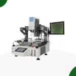 Rework Station
 Solder Paste Printers
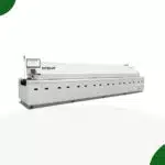 Reflow Ovens
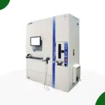 Reel Storage System
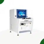 AOI & SPI INSPECTION
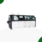 Soldering Machines
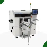 Insertion Machine
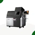 X-ray inspection
 PCB Handeling
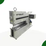 Depaneling Machine
