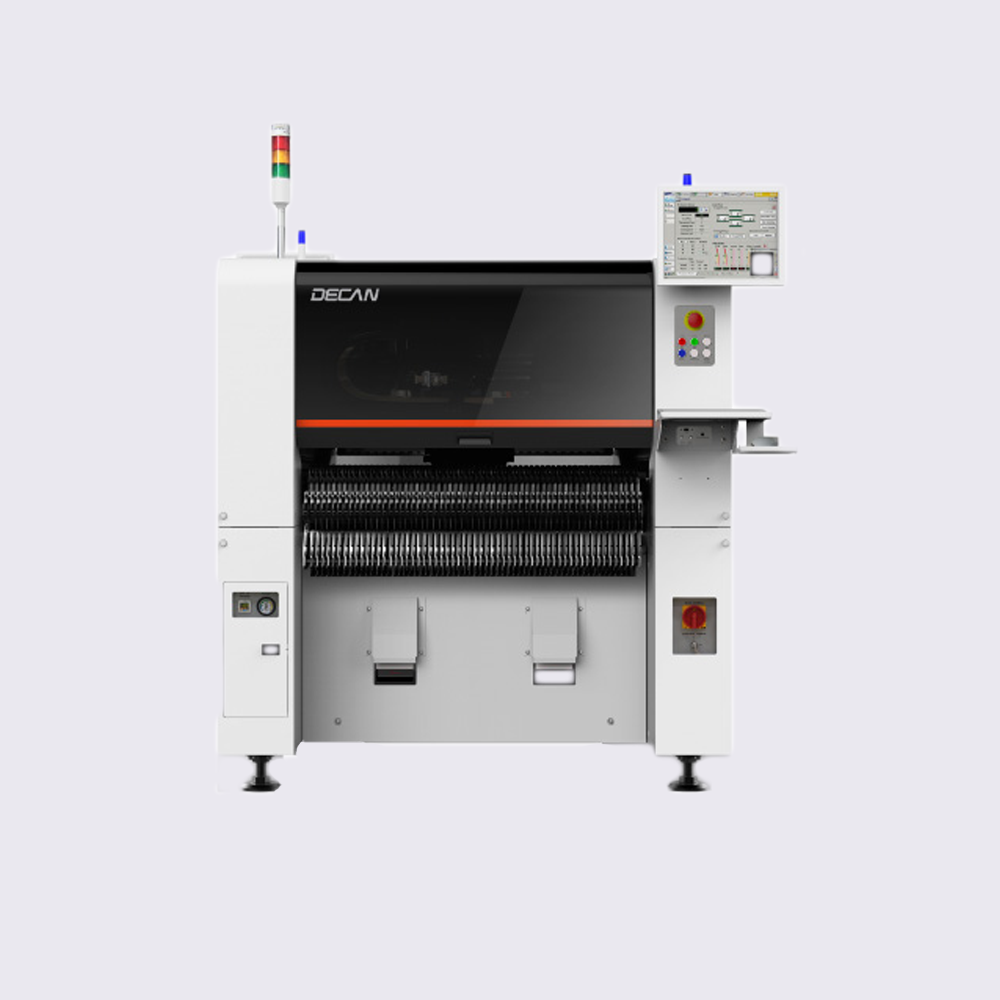
Improves actual productivity
• Improves placement quality
• Reduces loss rate
Highest Performance among Chip Mounters of the Same Class
Highest Applicability of Medium Speed Chip Mounters to PCBs
• 510 x 510mm (standard) / 1500 x 460mm (option)
– Possible to produce PCBs up to 1,500mm(L) x 460mm(W) in size
Expands the Component Recognition Range with a High Pixel Camera
• The fly camera can recognize all chips of 03015 ~ 16mm
Improves Simultaneous Pickup Rate
• Arranges pocket positions automatically through communication between the machine and feeder
Improves the Placement Speed of an Odd-Shape Component
• Increases speed by approximately 25% by optimizing the fix camera recognized motion sequence
Places Microchips Stably
Recognizes the Nozzle Center
• Improves the microchip loss rate and placement quality by preventing the occurrence of air leaks
Run Time Calibration
• Maintains placement accuracy by performing automatic calibration during production
Auto Maintenance Prevents Pickup Error and Maintains Placement Quality*
• Measures pneumatic pressure and flow rate of the nozzle and shaft
• Removes foreign materials on the nozzle and shaft by high pressure
air blast
Increased Convenience of Operation
Reduces the Teaching Time of a Large Odd-shape Component
• Expanded FOV of Fiducial Camera: 7.5mm → 12mm
– Reduces the time to teach the component pickup/placement point and improves the convenience of teaching
Maintains the Pickup Coordinate of the Common Feeder
• When changing a model, reduces the model changing time by succeeding the pickup information of a similar model
Unifies the Chip Component Lighting Level
• By setting the same lighting value collectively, minimizes the lighting changing time, removes the productivity deviation by machine and improves the convenience of part DB management
Support of Multi-vendor Component *
• It’s possible to manage the same components supplied by two suppliers in one part name, so it’s Possible to perform production continuously without changing the PCB program for the components supplied by different vendors
Teaches Large-sized Components Easily (Panoramic View)
• Performs split-recognition of a large-sized component that is out of
the camera recognition range (FOV) and merges split component images into a single image before displaying.
– Easily teaches the pickup/placement position of a large-sized component
* Since this is under development, it will be available for Auto Maintenance function in December 2018 and Multi-Vendor function in October 2018.
| CPH (Optimum) | 47’000 |
| Max. PCB Size (Standard) (mm) | 510 x 510 |
| Feeder Capacity (8mm) | 120 |
| Max. Component Height (mm) | 15mm |
| Max. Component Size (mm) | 55 x 55, 75mm Long Connector |
| Min. Component Size metric/imperial | 03015 |
| Optional PCB Sizes (mm) | 1500 x 460 |
| Placement Accuracy | +/-28um @3 sigma |

